Quantcast
Channel: LA3ZA Radio & Electronics
Viewing all 165 articles
Browse latest View live

The ultimate WSPR spot

$
0
0
A spot reported by K1JT must be the ultimate goal for the WSPR mode. K1JT, Joseph Taylor, is the Nobel laureate who first developed this mode and other related two-way modes like JT65 and JT9.

My 0.1 W 21 MHz WSPR transmitter regularly makes it over the Atlantic, but never before to K1JT. The SWR was something like 7:1, but apparently that works fine, both for the transmitter and for radiation.

The antenna is a 13 m doublet oriented with the broadside facing East-West (the EU spots in the figure are from my Ultimate 3 on 21 MHz with another antenna and at another location). I feed the doublet with 450 ohm ladder line to a 4:1 Elecraft balun which is connected to the Ultimate 2 transmitter.


Where can I get APF and DIV stickers for my K3?

$
0
0
The updated Elecraft K3, the K3S, has some nice improvements that would be nice to have, but which I also can live fine without. But even an old K3 can be updated to some of these improvements. They are detailed on the Elecraft K3S FAQ.

I studied the front panel for differences and put red rings around them. The three to the upper left have to do with the new display bezel with silver instead of black screws, the S in K3S, a built-in marker for the VFO A knob, and a soft-touch VFO A knob.

In addition to the marking with OFS (offset) to the left of the RIT/XIT control, there are two markings that also reflect what my present K3 with the latest firmware does:
  • APF instead of DUAL PB (Audio Peaking Filter - Dual Passband) - upper right
  • New marker for DIV - Diversity reception - to the left of VFO A
It sure would be nice to get stickers with APF and DIV to put on mine!

CQ WPX made my day

$
0
0
From time to time I have heard of those of who manage to contact 100 DXCC countries during one weekend. This past weekend it was my turn to try.

If you have a contest station with 1 kW and monoband yagi antennas, then this goal shouldn't be too hard. But for my station with only an 80 m horizontal loop (loop skywire) circling its way through my garden from treetop to treetop and 100 W of transmitter power from my K3, the challenge was greater.

About 6 hours before the end of the test and with 87 countries, I had almost given up so I sent the tweet above. The status for the second day of the contest was that I had only worked two more countries.

But then in the final hours I heard and then contacted Tunisia, Malaysia, Australia og Kosovo (Z6) to bring me to 91, and then Laos and Albania. But then it took a long while for some new ones: Spanish Africa (EA9) and Argentine. I also managed two more Caribbean stations (J3 and CO) and Peru and Sardinia.

Finally in the last hour of the contest two more Caribbean stations (PJ2 and VP9) and in the end Mexico 21 minutes before the end of the contest. That brought the total to 102. I think that was needed as Kosovo isn't really an approved country and I also had contact with what was probably a pirate and not a station from Andorra. That signature was C31XR which most likely is the name of an antenna and not a real station.

My total was 47 European countries, 19 from Asia, 12 from North America, 10 from Africa, 9 from South America and 3 from Oceania. I think it helps to be in Europe as I had almost half of the countries quite close by, but it would be interesting to hear comments from North Americans on how realistic they consider this goal to be from their location.

Regenerative receiver based entirely on the LM386

$
0
0
I got a tip the other day that there is an interesting circuit over at the RadioBoards Forum where an LM386 IC is used as a regen receiver for the medium wave band. It is the user 'Selenium' who has come up with that circuit. I think it is quite an amazing application of this IC - so here it is:
LM386 as a medium wave regen receiver by user Selenium on RadioBoards Forum

Interestingly, both the + and - inputs are tied together (pins 2 and 3). It is also quite unusual to connect pin 7 to anything but capacitors (for bypass or extra input as I have done), so that may change the bias of the input stage. Further, the smaller the impedance from pin 1 to ground, the larger the gain (here 10 uF in series with 1k for low frequencies and 100 pF for high frequencies).

If you want to read more about the regen circuit, go to the RadioBoards Forum here.

The LM386 Pixie challenge

$
0
0
The Pixie 2 is this minimal transceiver which I and many others have played around with and had lots of fun with. My 80 m version is shown to the right, but right now it is very popular with some incredibly cheap Chinese ones on sale on Ebay and other places.

The Pixie 2 uses the versatile LM386 amplifier for its audio output. I have shown previously on this blog how its gain can be boosted and how it can implement a CW filter, and also how the muting can be improved. However, during transmission, the LM386 just sits there idle, although it can be used to amplify a sidetone from an external oscillator.

But I'm sure the old 70's LM386 can do better than that. Despite its age, recently some pretty amazing uses of this chip have been demonstrated. It can be used as a regenerative receiver at least up to medium wave frequencies and it can also be used as an envelope detector/demodulator.

The LM386 challenge is this: Is is possible to implement a sidetone oscillator for the Pixie using only the LM386 with as few other components as possible? The output level needs to be controllable in order to make it comparable to that of the Pixie in the receiver mode.

The best data sheet for the LM386 seems to be the one for NJM386 from New Japan Radio Co. It is, as far as I know, the only one which shows the various muting circuits including the one using pin 7 which I have explored. It also shows the LM386 as an oscillator: both a sinusoidal and a square wave one.

In order for the LM386 to be useful as a sidetone oscillator, I believe that the oscillation must take place in the input circuitry. That seems to be the only way to ensure that the output doesn't come out at a blasting full rail-to-rail swing as in the square wave oscillator example in the data sheet.

By the way, the data sheet referred to above is also the basis for the improved Spice model for the LM386 that just was developed. It came partly as a response to my complaint over how poor the present one was. Maybe the new Spice model, developed by EasyEDA, could help solve the LM386 challenge?

Just good enough 10 MHz reference

$
0
0
Some time ago I noticed that the Ublox Neo-7M GPS has a 10 MHz output which is locked to the GPS system's accuracy. Most people kept saying how useless it was due to excessive jitter unless it was cleaned up with a phase locked loop of some sort.

But at the same time I installed the reference input for my Elecraft K3 (K3EXREF). It enables the K3's frequency to be locked to an external 10 MHz reference. What struck me was how its function was described:


This got me wondering if the Neo-7M would be just good enough as a reference and that all the averaging internally to the K3 would take care of the jitter.

I ordered one from Ebay for USD 12-13 together with an USB interface (USD 1.5) and hooked it up. (Actually the NEO-7M already has a built-in USB interface, but my board doesn't support it). The result is shown above as assembled in a clear top tin. In my wooden house I can receive GPS indoors, so I have no need for an external antenna

The K3 accepts the input and I see the star in REF*CAL blinking. Just after turn-on of the K3 my 49.38 MHz reference frequency ends in ...682 and after 10-15 minutes it has fallen and stabilized to ...648, i.e. 34 Hz down in frequency. This is just 8 Hz off the reference value I determined manually was the right one when my K3 was new in 2009 (49.379.640).

All this taken together indicates to me that the K3 finds this 10 MHz acceptable for locking. The measurement to the nearest Hz, implies a measurement time of the order of 1 second and that seems to be enough to smooth out the jitter from the Neo-7M.

In order to get this to work I had to do some modifications to the GPS unit. First I had to get access to the timepulse on the chip's pin 3. My connection is inspired by that of G4ZFQ and consists of a small wire from the left-hand side of the 1k resistor to the upper left hole. From there another grey wire goes below the chip and to the 5-pin header which is soldered to the Vcc, Rx, Tx, Gnd pins. The 5th pin is cut off and is just attached to the other pins through the plastic hardware.

The second modification was required in order to get it to run from the somewhat noisy USB 5 Volt supply. That took some decoupling between the Vcc and Gnd pins (220 uF and 0.1 uF in parallel), visible to the right in the image above, using good engineering practice to keep the wires as short as possible.

The timepulse is a 3.3 Vp-p output which cannot drive anything below 4-500 ohms impedance. Therefore I added a 74HCT04 driver that I have assembled on a little homemade SMD to DIL adapter PCB (easy to find on Ebay). It serves as a driver to feed the 10 MHz to the 50 ohm input of the K3EXREF.

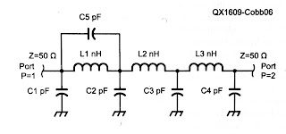
The HCT04 IC has 6 inverters. One of them takes the input signal from the Timepulse output of the GPS IC and buffers it to drive the 5 other inverters in parallel. This is shown in the schematics at the end of this blog post.

The 5Vp-p output from the buffers is fed via 56 ohms to a connector that goes to the K3EXREF input. This is in accordance with the K3EXREF manual which says: "The 10 MHz source should have a signal level between +4 dBm and +16 dBm, nominal. For square wave sources, 2VDC to 3.3VDC peak is optimum. If the source is a 5V logic level, use a 50-ohm resistor in series with the input."

In order to set up the GPS I have used the u-center program (Menu: View, Configuration View, TP5 (Timepulse 5)) from Ublox and set it up with the parameters shown to the right. It blinks at 4 Hz before the signal is acquired and then switches to 10 MHz. This can be observed on the green LED connected to the Timepulse output also as it switches from blinking to a half-lit status. 

The Neo-7M can store these parameters, but annoyingly it seems to forget them after half a day or so. Apparently the supercap on the module does not hold its voltage well enough, so then I have to enter the parameters again and press the Send at the bottom left.

The Ublox Neo-7 GPS is a lousy frequency reference in most respects, except that it is accurate in keeping exactly 10 million periods per second. My experience is that the K3 has enough internal averaging to deal with that. This is despite the fact that the 10 MHz output frequency is actually one of the worst when it comes to phase noise as it doesn't divide evenly down from the internal 48 MHz (6, 8, 12, ... MHz are much better) as measured by RA3APW (access his site with Chrome and use the translate feature).

I have only tried this on the Elecraft K3, but I wonder how many of the other transceivers out there which have similar internal averaging and that will find the 10 MHz output from the Ublox Neo-7M acceptable?


Better with SMA

$
0
0
I had some trouble closing the lid on the "Just good enough 10 MHz reference" due to the size of the BNC jack. Therefore I changed it to an SMA (SubMiniature version A) female jack. A thin cable connects it to the K3's SMA input and there is no need for any SMA-BNC adapter on that end.

At the same time I moved the GPS antenna to a more central location in the tin, in the hope that the walls of the tin would interfere less with GPS reception. That's the theory anyway, if it matters much in practice is a different story.

Actually, I think I'm going to use SMA more often with these clear top tins and also Altoids tins. They take up much less space and are easier to install and to work with.

There aren't any high power applications for circuitry in such tins, so I cannot so any reason why the SMA won't work just as well or even better than the BNC.

Radio Ghosts Have Haunted the Airwaves for Nearly a Century

$
0
0
“The starship hypothesis is a very interesting one, and the one which seems to be the most popular one on the internet,” said Sverre Holm, a professor of signal processing at the University of Oslo. “Such theories always excite our imagination, but it builds on a very poor data set. Unfortunately I believe it says more about human imagination than anything else.”

Although scientists have yet to settle on a final explanation for these mysterious echoes, Holm believes this is has less to do with a lack of scientific knowledge than a lack of willpower.

“I think that with today’s satellites and sensors, the mystery of Long Delayed Echoes (LDEs) could probably be solved,” he said. “What’s holding us back is most likely the problem is not considered important enough—it doesn’t occur often enough and doesn’t affect important enough forms of communications.”

These are excerpts from an interview in an article entitled "Radio Ghosts Have Haunted the Airwaves for Nearly a Century" on Motherboard Vice written by Daniel Oberhaus.

Curing amnesia in the 10 MHz GPS reference

$
0
0
Just good enough 10 MHz GPS reference with
u blox Neo-7M GPS module to the upper right,
10 MHz output buffer lower right,
USB interface to the upper left,
CR2032 lithium battery center left,
GPS antenna in the center,
and SMA output connector lower left.
My just good enough 10 MHz GPS reference which drives the external clock input on my Elecraft K3 kept losing its configuration if power was off for a day or so. I have therefore fitted a CR2032 3V lithium battery as seen to the left in this image.

It is connected in series with a 1N4148 diode in order to prevent attempts at charging the lithium cell. The connection goes to pin 22 (V_BCKP) as described by G4ZFQ on his website. The diode is visible to the upper left of the battery.

With this, I consider the 10 MHz reference to be finished.

Earlier related posts:

Finally got rid of the pirated USB chips for the UV-5R and the AP510

$
0
0
Both the Baofeng UV-5R handheld UHF/VHF radio and the Sainsonic AP510 APRS tracker come with interface cables with pirated chips. These are clones of Prolific USB/serial chips. Since Prolific has taken measures against this, only old drivers will work with them. That means that one has to stop automatic driver updates as explained on the Miklor site for the Baofeng UV-5R. The same is true for the AP510. This is a nuisance.

I got tired of this and got myself some USB/serial modules from Ebay based on the CP2102 chip instead. The cost was US $1.43 a piece so it should be affordable for anyone. I also got some clear heat shrinkable tube.

It wasn't too hard to follow the instructions on the Miklor site. I ended up replacing the chip in the original Baofeng serial cable. I'm a hardware guy so I think it is a shame not to see the three LEDs for power, rx, and tx so I used my Dremel to make a 12x12 mm cut-out in the original case, and then I closed it by using transparent shrinkable tube. For a picture, see the top of the first image.

If it doesn't work the first time, exchange rx and tx and see if that works better. According to this site, the boards can be marked just opposite of what you might think.

The Sainsonic AP510 APRS unit has a cable that on first sight just looks like a standard USB cable, but it also contains such a chip. Here I made a completely new cable without any case.  It is important that 5 Volts also passes through as this is used for charging. The pinout can be found on the site of DJ7OO (use Google translate if needed). I enclosed the board in shrinkable tube which is transparent enough for the LEDs to shine through as seen in the bottom of the first image. The board with the fake chip is found in the middle. 

So now I have interface cables for both units that don't require me to stop updates of drivers or any other special precautions and it is much easier to program the devices from any PC.

Magnetospherically ducted echoes in the San Francisco area

$
0
0
On 7. November 2015, several radio amateurs in northern California heard echoes in the 80 meter band. I was made aware of it by Jack, W6FB in Santa Clara, who recorded signals from K6YT some 25 miles away. According to W6FB, the echo effect was also heard north of Sonoma (several hundred miles north of him, reported by N6ZFO).

KM6I, Gordon, in Palo Alto also heard echoes of his own signals and recorded them. In his blog he analyzed the delay from the output of his transceiver and found 157 ms. He found that to be so close to the round-the-world time for signals of 138 ms, that he assumed that to be the cause.

I don't agree, so I took the location of W6FB at locator CM97ah (Santa Clara) as a starting point for computing delay. This is latitude 37.31 and longitude -121.96 and gives a geomagnetic latitude of about 42.5 degrees. Then I put it into my program for computing path length along geomagnetic field lines assuming a height of the reflecting ionosphere on the opposite side of 100 km. The result is shown in the figure and predicts a delay time of 126 ms. My estimate of uncertainty is +/-5 ms.

The delay value is slightly less than 138 ms and easy to confuse with a round-the-world path. The challenge with estimating delays like this from the signal is that amateur transceivers may have an unspecified delay between start of transmission and start of sidetone. Measuring on the audio output as done here, measures the sidetone, not the actual RF.

I discussed this source of error in my 2009 QST article "Magnetospheric ducting as an explanation for delayed 3.5 MHz signals." Therefore the measurement shown above may fit with 138 ms just as well as with 126 ms, it depends on the actual transceiver's delay.

Other properties of the echo, such as the amplitude of the echo which according to W6Fat times was louder than the direct signal, also point to the duct theory as the explanation.

Others have heard such echoes also:
Other posts on the theme: Magnetospherically Ducted Echoes or Medium Delayed Echoes

Latest firmware for AP510 APRS tracker is superb

$
0
0
I got my AP510 APRS tracker a little more than a year ago. It kind of worked, but not very well in my car. But after the tracker got a new firmware dated 3 Nov 2015, it has become so much better. Now I can say that it is really useful.

Apparently, the Smartbeacon function didn't work properly in earlier versions of the firmware. With some good debugging and error reporting by KC5EVE, Mark, working with the software developer for the AP510, BG6QBV, the annoying errors now seem to be gone. This is all documented in the Yahoo AP510 group.

I have fitted mine with a 16-45 cm telescopic antenna and even when attached to one of the rear headrests in my sedan, the 1 Watt of output power tracks very well.

The map below shows a drive from Telemark, about 100 km west of Oslo, to Oslo with as good coverage as one can expect given the valleys and the availability of APRS digipeaters on the way.


Series capacitors that failed according to the book

$
0
0
0.33 uF X2 capacitors which measured only
0.097, 0.1, and 0.118 uF.
Many devices now use a capacitor power supply saving the space that a mains transformer occupies. The principle is that a series capacitor from the mains supply is used to drop the voltage and reduce the current. Provided that the circuit is completely isolated from human touch, this is an economical way to provide DC power.

The image shows three such capacitors as I were measuring them. They came from three malfunctioning devices in my home: two wall-mounted thermostats for floor heating and a remote controlled mains switch.

Their power supplies were designed with a capacitor of 330 nF in series with a bridge rectifier which supplies the low voltage DC. This value is typical, it seems for 230 Vac, 50 Hz circuits that are designed for about 20 mA. The value will be higher for an equivalent 115 Vac, 60 Hz circuit.

The malfunctioning happened because the value of the capacitor in my cases was reduced to 1/3 and less of the nominal value. These capacitors are all marked X2 and a voltage of 275 Vac.

The X2 means that they are safety capacitors which will not fail by short-circuiting as this would be a fire hazard in this circuit. They have self-healing properties and that means that they fail by "burning away" on their own foil, leading to a reduction in capacitance and eventually failure of the circuit as the power supply cannot supply the required current any more. They should never be replaced by anything but X2 capacitors with the same or higher voltage rating.

Go to the Wikipedia page Capacitive power supply for more description of this circuit.

By the way, the devices which these capacitor came from were 15 year old Microtemp MTN-1991 thermostats and a 20 years old Nobø System 500 RCE512 remote receiver.

Teeth marks in the K3

$
0
0
DX-expeditions love their K3s. And I love my K3. But look closely at the MENU button and you will find the marks of someone who literally have put the K3 on their menu as well.

Neither has the BAND button escaped this. Judging from the size of the teeth marks it is perhaps not so hard to guess who did this.

This is our club station's K3 and off weekends the only inhabitants there are mice, who seem to have taken their fancy on the soft buttons of the K3. They let every other piece of equipment alone, such as the Yaesu FT-1000MP, so there is definitely something special about the K3. I would guess that this was not part of the original Elecraft design specifications for these buttons.
The remedy is shown here: A custom-designed acrylic cover that is fitted on the K3 whenever it is not in use.


This article originally appeared on the LA3ZA Radio & Electronics blog.

Improved GPS reception with a ground plane

$
0
0
My poor-man's 10 MHz reference based on the Ublox Neo-7M GPS module didn't always receive GPS satellites. Since I rely on reception indoors, conditions were sometimes too marginal to lock the oscillator output to 10 MHz. Inspired by the QRPlabs GPS module of Hans Summers (G0UPL) with its large 6 x 6 cm PCB groundplane, I therefore decided to do something similar.

The first picture shows the unit with the 8.5 x 6.5 cm single-sided PCB ground plane attached with double-sided tape. It definitely helped make indoors reception in my shack much more reliable. In addition to the improved conditions for the patch antenna, it probably helps too that the antenna now is shielded from the digital circuitry of the GPS module, the 10 MHz pulse shaper, and the USB interface. I also added a small LED to the right so that I could see from the outside whether the GPS locks properly.

The second picture shows the interior prior to adding the ground plane.

This post is a continuation of these other posts about the 10 MHz reference:
  1. Just good enough 10 MHz reference (3 Oct 2015)
  2. Better with SMA (15 Oct 2015)
  3. Curing amnesia in the 10 MHz GPS reference (19 Nov 2015)


DIY Powerpole voltage and current meters

$
0
0
Powerpole voltage and current monitoring is quite nice to have. One can buy commercial meters, but due to the availability of nice and cheap modules, it is very easy to make them oneself.

To the right you'll see my combined voltage and current meter as well as my volt-meter on top of the power supply.

Both of the modules have been bought on Ebay:
  • Miniature 0-30 V DC LED 2 wire Digital voltmeter (371333527599) where the display is 22 by 10 mm. Cost slightly more than $1
  • 0-100 V, 0-10 A Dual Voltmeter Ammeter (262455987311) costing less than $3. The module size is 48 x 29 x 26 mm and the letters are 7 mm tall just like the miniature voltage display.
The wires to the voltmeter are connected directly to Powerpole connectors as shown in the second figure (upper right). Then the voltmeter itself is enclosed in transparent shring-wrap tubing of diameter approximately 20 mm like the one you also can buy on Ebay (252004328030).

The voltage-current meter is a little more complex to connect. First the volt meter has a power lead (4-30 V) and a measurement lead (0-100 V) which are connected together as I will only be using it for 12 Volts. The current measurement loop is between the negative, black, Powerpole connectors. The positive, red, Powerpole connectors are wired together.

I hope this can inspire others to make something similar. And if you do, then please let me know in the comments field!


What it takes to make the AP510 APRS tracker useful

$
0
0
This small VHF APRS tracker can easily be improved with some simple measures:
  1. The 1 Watt of output power is often too little to reach the desired APRS digipeater reliably enough. It is much simpler to improve the antenna than to add an amplifier and it can be done as follows:
  • Use a longer telescopic antenna. In the picture I have used an antenna that can be extended from 16.5 cm to 45.2 cm. Depending on how you use the tracker, always extend the antenna as much as practically possible.
  • Add an external counterpoise or "tiger tail" of length a quarter of a wavelength. That's about half a meter. In the picture it is fastened on the antenna's BNC connector by means of an 8 mm ring terminal.
  • Update the firmware, if you haven't done so already, to the version from 3 Nov 2015. I have written before about my experience with that firmware.
  • Get rid of the pirated USB chip in the interface cable. I did that last year and now interfacing it to the PC and updating it is so much simpler.
  • These simple steps have made my AP510 tracker much more useful.


    The post "What it takes to make the AP510 APRS tracker useful" first appeared on the LA3ZA Radio & Electronics Blog.


    Yet another Arduino clock

    $
    0
    0
    Does the world need more Arduino clocks? Maybe not. But I needed another Arduino project as I had made a K3NG morse keyer. I love this keyer because it is unique in supporting a display where you can see what you send.

    But I wasn't using the morse keyer all the time, so I wanted the hardware to serve two purposes. That's the excuse for also making a clock. Its main features are:
    The hardware for the K3NG keyer includes a speed pot and a memory bank selector (to the right) as well as four push buttons on top for selecting memories. These controls are not used by the clock, except for button 1. With it I can toggle the clock through various displays as shown below.

    Local time, solar and lunar state
    Line 1: Local day, date, time
    Line 2: Sunrise, maximum solar elevation (actual solar angle during the day), sunset
    Line 3: Civil dawn, local time at maximum solar elevation, civil dusk
    Line 4: Lunar phase, arrow showing that it is rising, days since new moon


    UTC and position display
    Line 1: UTC time, locator
    Line 3: latitude, longitude
    Line 4: Altitude, number of GPS satellites
    Dual time display with local time, UTC time, and locator

    What I would like to have as well is an indication of lunar visibility at the actual location with azimuth and elevation for the moon. So far I haven't had success in finding a suitable Arduino library for that, but I'm hoping that a reader of this blog may help me.


    The post "Yet another Arduino clock" first appeared on the LA3ZA Radio & Electronics Blog.


    Even better low-pass filters for transmitters

    $
    0
    0
    The last issues of QEX have featured two interesting articles by Gary Cobb, G3TMG. He outlines the advantage of using Zolotarev designs for the harmonic suppression filters of transmitters, giving even better suppression of the second harmonic than the more common Chebyshev or quasi-elliptic filters.

    Chebyshev low-pass filter from the GQRP data sheet (issue 1)
    My interest in this was triggered by the test of the Ultimate 3 QRSS/WSPR kit from QRP Labs in the Nov 2016 QST. The review was positive overall, but it was remarked that the harmonic suppression does not meet FCC requirements (-43 dBc or better). I am not sure whether this is due to PCB layout issues, or if better filters can alleviate it, but I note that the design uses the simplest filter of the ones I have listed here.

    The evolution of filters for use for harmonic suppression follows at least these three steps:
    1. Chebyshev type I filters with equiripple in the passband and a monotonically falling, maximally flat stopband. A 7-pole version with three inductors and four capacitors in a pi-network has been around for a while, in e.g. the old recommendation from the GQRP club. It was based on the QST paper "Low-pass filters for amateur radio transmitters," Ed Wetherhold, W3NQN, Dec. 1979. Two designs for a 20 m filter were given there:
      1) Max. ripple in passband: 0.00731 dB, attenuation at 28 MHz: 40.7 dB
      1) Max. ripple in passband: 0.00960 dB, attenuation at 28 MHz: 34.5 dB

    2. Second-harmonic optimized low-pass filter from the
      GQRP data sheet (issue 2)
      An improved stopband was the topic of W3NQN's article "Second-harmonic optimized low-pass filters" in QST Feb. 1999. Here there is one additional capacitor as the central inductor is made into a parallel resonance which gives a zero in the stopband, based on an idea by Jim Tonne, WB6BLD. The design goal is that this zero should be at the second harmonic frequency. W3NQN proposed to call this a Chebyshev filter with a zero (CWAZ) filter, but it is more correct to call it a quasi- or pseudo-elliptic filter as remarked by G3TMG. It increases the attenuation at the second-harmonic in the 20 m design to better than 60 dB. This design is the basis for the current (Issue 2) G-QRP technical sheet. This would also be interesting to test in the QRP Labs Ultimate 3 transmitter kit.

    3. Zolotarev low-pass filter from the Nov/Dec 2016 QEX article
      G3TMG in the new QEX articles has noticed that the passband is over-specified in the above filters as the lower 60% or so of the passband is unused. The Zolotarev design allows for more passband ripple in this part where it does not matter. The advantage is even better stopband attenuation. A measured example for a 60 m filter has a passband ripple of 0.17 dB and a stopband attenuation at the second harmonic of 71 dB. This filter has the same component count as the previous one, but the filter is no longer symmetric like the two previous ones. The increase in second-harmonic suppression is not as great as the going from the first filters to the second, but should still be worth the effort.
    The papers, which are well worth reading, are:
    • Gary Cobb, G3TMG, Zolotarev low-pass filter design, QEX, July/Aug 2016.
    • Gary Cobb, G3TMG, A more efficient low-pass filter, QEX, Nov/Dec 2016.

    Comparing two antennas with WSPR

    $
    0
    0
    Ultimate 3S with 5-band relay module in front,
    variable LM2596 power supply (with voltmeter) for
    the power amplifier behind left,
    a variable LM2596 supply set for 5 Volts for the Ultimate 3S
    in the middle, and the antenna switch to the right in the back.
    WSPR - The system for Weak Signal Propagation Reporter makes it easy to compare antennas if your transmitter can instantly switch antennas. The system shown here can send on antenna 1 for almost two minutes and then switch immediately to antenna 2 for the next transmission.

    The Ultimate 3S already has software that supports that and application note 3 from QRPLabs (Controlling additional relays using the Ultimate3S “Aux”) describes how. I built mine following that note and the experience from EA1CDV.

    The circuit is controlled from pin D7 and consists of a transistor, a relay, a resistor and an electrolytic capacitor. In addition I have two LEDs that indicate which antenna which is in use. In the first picture the green LED in the back right under the BNC antenna connector shows that antenna 1 is connected.


    In the next picture, the whole layout is shown a little better. In this case LED 2 is lit, the faint yellow one. It sits right under the additional SMA antenna connector in the top left-hand corner that I had to fit.

    I have used this setup for a few days now on 7, 10, 14, and 18 MHz with some crossed doublet antennas (somewhat like this setup, but not in the same location). I change the frequency between antennas, e.g. 50 Hz below the center frequency of the band for antenna 1 and 50 Hz above for antenna 2 in order to simplify discrimination between the transmissions.

    The short 13 m antenna transmits best East-West, and the longer 26 m antenna North-South. The directivity is in general confirmed by the WSPR reports I see. Sometimes the difference can be more than 10 dB in SNR, but more often it is closer to 5 dB. But it also happens that only one of the transmissions is detected. This should make for some interesting analysis in the coming months.


    The post "Comparing two antennas with WSPR" first appeared on the LA3ZA Radio & Electronics Blog.
    Viewing all 165 articles
    Browse latest View live