The trusty old LM386 audio amplifier from the 70's is still used a lot in low power and portable equipment. Recently some ultra high gain circuits have been recommended that I wanted to simulate with Spice. I started with the datasheet examples for checking the quality of the model. The result was surprising.
In the data sheet one can find a minimum parts circuit, a high gain circuit, and a bass boost circuit:
There isn't any official Spice model available from the manufacturer of the chip, at least not that I have been able to find. But there is a "no-frills LM386 model" attributed to Dave Dilatush (5/30/95) so I used that and a put it in a separate LM386.sub file.
The Spice code is quite simple and listed at the end of this posting. The result is shown here in two sets of curves. The first is for the 26 dB and 46 dB amplifiers.
The first result is in the left-hand curve which shows that the high-gain version has problems with the low frequency response, so I increased the 10 μF feedback capacitor to 100 μF in the right-hand plot (between pins 1 and 8). That makes the plot almost as flat as that of the data sheet down to 100 Hz.
Second, the high frequency response is too high in the simulation compared to the data sheet shown below. The Spice model does not seem to have enough high-frequency roll-off.
Third, close inspection shows that the gain of the high-gain amplifier (the blue curve) levels off at 45.4 dB, not 46 dB. This should indicate that the open-loop gain of the Spice model is not high enough.
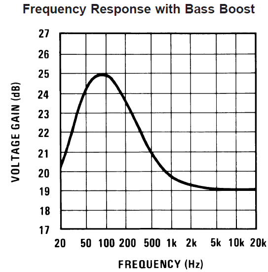
For comparison, the data sheet plots the responses as follows:
![]() Finally here is the simulation of the bass boost. It is actually quite close to that of the data sheet, probably because the gain is not very high and the original plot only goes to 20 kHz.
Finally here is the simulation of the bass boost. It is actually quite close to that of the data sheet, probably because the gain is not very high and the original plot only goes to 20 kHz.
In conclusion, in order to do simulate the LM386, there is a need for a Spice model with more roll-off at high frequencies and with a higher open loop gain.
I also observe that there is a constant current source in the LM386 model of value i1=5 mA. It must for sure be too high since the data sheet says that the quiescent current for the entire chip is min. 4 mA, max 8 mA.
Before there is any point in simulating the "Unleashing the LM386"-circuit that I introduced in Sprat (autumn 2003) or the simplified version that SM7UCZ (Johnny Apell) introduced in Sprat this spring - both based on the circuit of JF1OZL (Kazuhiro Sunamura), the Spice model needs some improvement. These circuits are also in George Dobbs, G3RJV's articles in Practical Wireless, May and July 2014.
Actually I knew that improvements are needed since I have already tried with inconsistent results. But I have the hope that some of the readers may steer me towards an improved model.
Links:
Spice code for use with TopSpice or LTSpice:
Spice circuit for the LM386 (store in LM386.sub):
In the data sheet one can find a minimum parts circuit, a high gain circuit, and a bass boost circuit:
 |  |  |
Gain = 20 (26 dB), minimum parts | Gain = 200 (46 dB) | Bass Boost |
There isn't any official Spice model available from the manufacturer of the chip, at least not that I have been able to find. But there is a "no-frills LM386 model" attributed to Dave Dilatush (5/30/95) so I used that and a put it in a separate LM386.sub file.
The Spice code is quite simple and listed at the end of this posting. The result is shown here in two sets of curves. The first is for the 26 dB and 46 dB amplifiers.
The first result is in the left-hand curve which shows that the high-gain version has problems with the low frequency response, so I increased the 10 μF feedback capacitor to 100 μF in the right-hand plot (between pins 1 and 8). That makes the plot almost as flat as that of the data sheet down to 100 Hz.
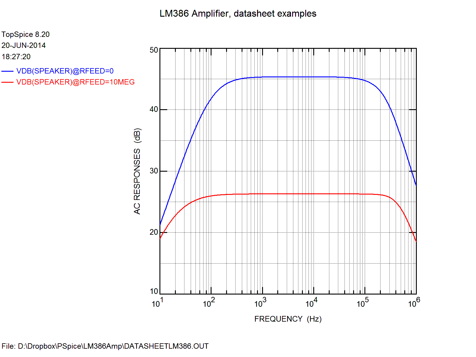 |  |
| 26 and 46 dB amplifiers according to data sheet | 26 and 46 dB amplifiers with 100 uF in the feedback |
Second, the high frequency response is too high in the simulation compared to the data sheet shown below. The Spice model does not seem to have enough high-frequency roll-off.
Third, close inspection shows that the gain of the high-gain amplifier (the blue curve) levels off at 45.4 dB, not 46 dB. This should indicate that the open-loop gain of the Spice model is not high enough.
For comparison, the data sheet plots the responses as follows:
 |  |

In conclusion, in order to do simulate the LM386, there is a need for a Spice model with more roll-off at high frequencies and with a higher open loop gain.
I also observe that there is a constant current source in the LM386 model of value i1=5 mA. It must for sure be too high since the data sheet says that the quiescent current for the entire chip is min. 4 mA, max 8 mA.
Before there is any point in simulating the "Unleashing the LM386"-circuit that I introduced in Sprat (autumn 2003) or the simplified version that SM7UCZ (Johnny Apell) introduced in Sprat this spring - both based on the circuit of JF1OZL (Kazuhiro Sunamura), the Spice model needs some improvement. These circuits are also in George Dobbs, G3RJV's articles in Practical Wireless, May and July 2014.
Actually I knew that improvements are needed since I have already tried with inconsistent results. But I have the hope that some of the readers may steer me towards an improved model.
Links:
- Dave Dilatush no-frills LM386 model.
- Comments on the quality of the LM386 Spice model.
- Datasheet for LM386
Spice code for use with TopSpice or LTSpice:
LM386 Amplifier
*
*
* LM386 Data Sheet curves simulated in TopSpice
* Sverre Holm (LA3ZA), 20 June 2014
*
**********************************
.include lm386.sub

* Step through 26, 34, 46 dB
cfeed nc4 10010uF
*rfeed nc3 100 {Rvar};     LTSPice
*.STEP param Rvar LIST 0.0110Meg;          LTSpice

rfeed nc3 10010Meg;     TopSPice
.STEP Rfeed LIST 010Meg;    TopSpice

* Comment out for flat response (default)
*Xfeed nc3 output BassBoost

.probe
.ac dec 100101e6 ; 100 steps per decade from 10 Hz to 1 MHz
*.tran 1u3m 05u
.save vdB(speaker)
*.print ac V(speaker);  LTSpice
.print ac vdB(speaker); TopSPice

vsupply vcc 0 dc 9
rsupply vcc vs 10
csupply vs 0470uF

vsignal inn 0 ac 1 sin 0.051k
rplus nc1 01e-6

* Output circuitry
csnub output snub .05uf
rsnub snub 010
ccoupling output speaker 250uf
rspeaker speaker 032

xamp inn nc1 nc2 nc3 nc4 output vs 0 lm386

cbypass nc2 00.1uf ;bypass cap for PSRR

************************************************************
* Bass boost (in LM386 Data Sheet)
.subckt BassBoost nc3 output
cfeed output 1033nF
rfeed nc3 1010k
.ends BassBoost
************************************************************
.end
Spice circuit for the LM386 (store in LM386.sub):
* NO-FRILLS LM386 MODEL
* Dave Dilatush 5/30/95
*
*http://groups.google.com/group/sci.electronics/browse_thread/thread/4acbf7a7f3c36b0f/db8514b79b5b1709
*

* lm386 subcircuit model follows:

* IC pins:23718564
*||||||||
.subckt lm386 inn inp byp  g1  g8 out  vs gnd

* input emitter-follower buffers:

q1 gnd inn 10011 ddpnp
r1 inn gnd 50k
q2 gnd inp 10012 ddpnp
r2 inp gnd 50k

* differential input stage, gain-setting
* resistors, and internal feedback resistor:

q3 100131001110008 ddpnp
q4 1001410012 g1 ddpnp
r3 vs byp 15k
r4 byp 1000815k
r5 10008 g8 150
r6 g8 g1 1.35k
r7 g1 out 15k

* input stage current mirror:

q5 1001310013 gnd ddnpn
q6 1001410013 gnd ddnpn

* voltage gain stage & rolloff cap:

q7 1001710014 gnd ddnpn ;
c1 100141001715pf

* current mirror source for gain stage:

i1 10002 vs dc 5m
q8 1000410002 vs ddpnp
q9 1000210002 vs ddpnp ; diode

* Sziklai-connected push-pull output stage:

q10 1001810017 out ddpnp
q11 100041000410009 ddnpn 100 ; diode D1
q12 100091000910017 ddnpn 100 ; diode D2
q13 vs 10004 out ddnpn 100
q14 out 10018 gnd ddnpn 100

* generic transistor models generated
* with MicroSim's PARTs utility, using
*default parameters except Bf:

.model ddnpn NPN(Is=10f Xti=3 Eg=1.11 Vaf=100
+ Bf=400 Ise=0 Ne=1.5 Ikf=0 Nk=.5 Xtb=1.5 Var=100
+ Br=1 Isc=0 Nc=2 Ikr=0 Rc=0 Cjc=0p Mjc=.3333 ;
+ Vjc=.75 Fc=.5 Cje=5p Mje=.3333 Vje=.75 Tr=10n ;
+ Tf=1n Itf=1 Xtf=0 Vtf=10) ;

.model ddpnp PNP(Is=10f Xti=3 Eg=1.11 Vaf=100
+ Bf=200 Ise=0 Ne=1.5 Ikf=0 Nk=.5 Xtb=1.5 Var=100
+ Br=1 Isc=0 Nc=2 Ikr=0 Rc=0 Cjc=0p Mjc=.3333 ;
+ Vjc=.75 Fc=.5 Cje=5p Mje=.3333 Vje=.75 Tr=10n ;
+ Tf=1n Itf=1 Xtf=0 Vtf=10) ;
.ends
*----------end of subcircuit model-----------