Quantcast
Channel: LA3ZA Radio & Electronics
Viewing all 165 articles
Browse latest View live

Simple interference fix for the Chinese Pixie

$
0
0
The Chinese Pixie transceiver operating at 7023 kHz has become very popular. It often costs less than 5 USD on Ebay. Like most Pixies it is susceptible to broadcast breakthrough and intermodulation. Much of this is caused by the keying circuit of the audio amplifier, the LM386. The cure is to move the muting diode from the power supply pin (no. 6) to the bypass pin (no. 7). I have described this in another blog post with title: "Using pin 7 of the LM386 to reduce BCI and add side tone to Pixie 2".

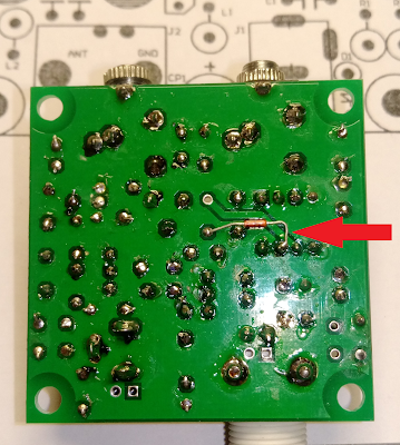
Here are two pictures that show how this can be done for the Chinese Pixie. One needs an additional resistor in the range 10 - 51 ohms. If you can fit it, then use the large 51 ohms resistor that come with some of the kits (I think it is meant for a dummy load). I have used 10 ohms in the picture. It replaces the old R3 of 1 k. The diode D3 is not mounted in the holes provided, and instead it is mounted under the PCB with the minus (denoted by the ring) connected to where D3's minus was, and the plus side connected to pin 7 of the LM386.

R3 is indicated by the lower left arrow, and the old
placement of D3 is shown with the upper arrow
Arrow showing where D3 instead should be soldered.
The minus, indicated by the ring, is to the left in the image

The post "Simple interference fix for the Chinese Pixie" first appeared on the "LA3ZA Radio & Electronics Blog."


FT8 anomaly or long delayed echo?

$
0
0
My friend Alf, LA2NTA, has sent me these screenshots from when he has been operating FT8. The first image is when operating 10 meters and took place early in November.

Two of LA2NTA CQs being received by himself on 10 meter (in red)

It shows how his own CQ comes back to him at 10.54.00 and at 11.00.00 and is decoded in his own receiver. The echoes return at the time of transmission.

The second example is from 20 meters and took place just a few days ago.

LA2NTA CQ being received by himself on 20 meter (in red)

For the first example he also took an image of the spectral display. It shows lots of repeated noise burst all over the FT8 band.

FT8 band on 10 meters showing some form of noise all over the band

It is hard to explain this, but my hunch is that it is something local and not a propagation phenomenon, but who knows?


QRSS experiments: FSKCW and Slow Hell

$
0
0
These last few days I've been experimenting with my QRPLabs Ultimate 2 and Ultimate 3s transmitting on 7 MHz. In addition to WSPR, the modes transmitted have been FSKCW with 6 second long dots, and Slow Hell with 17 second long characters. The result as received this morning can be seen on the display from the grabber of Les, G3VYZ in Northumberland, UK. This is a stack of 6 consecutive 10 second frames as can be found on the QRSS grabber site of AJ4VD.

FSKCW and Slow Hell reception of LA3ZA at G3VYZ

My signal is on 7,039.870 kHz and has been set up with a FSK shift of 6 Hz. Power output was 0.2 W and the distance is about 890 km.

It works but the reception is much less reliable than for WSPR, which is not so unexpected. At the same time the WSPR signal was received all around Northern Europe (G, GM, DL, ON, OE, LX, LA, OY, OH, PA, SM) as well as on the Canary Islands, 3930 km away.

Deteriorating ceramic filters due to DC

$
0
0
Tandberg Huldra 10
Tasos, SV8YM, has written about "The Mysterious Case of the Withering Filters". This seems to affect not only ham radio transceivers, but FM stereo receivers as well.

Tandberg from the 70's are collectors items and since I actually worked one summer at Tandberg in the early 70's they bring back good memories for me. The latest generation of receivers (2nd version of Huldra 10, Huldra 11, and Huldra 12) had ceramic filters for the 10.7 MHz intermediate frequency for FM. It is also known that these filters deteriorate leading to reduced sensitivity over time.

SV8YM has pointed out that ceramic filters deteriorate due to DC on the terminals, especially the output terminal and that this leads to electromigration. In the Huldra 10, both filters have 7.1 V DC on the input. Filter F1 has 0 V DC on the output, while F2 has 2.1 V on the output.

Old filters (left) and new filters

As I got ready to replace mine with new Murata filters (SFELF10M7GA00-B0, 230 kHz bandwidth), I read the same warning in their specifications, which says: "For safety purposes, connect the output of filters to the IF amplifier through a D.C. blocking capacitor. Avoid applying a direct current to the output of ceramic filters."

I also noticed that the filters had been replaced before. To be sure, I added three coupling capacitors (10 nF - 0.01 uF). This value has a reactance of 1/(2 pi 10.7e6 0.01 e-6) = 1.5 ohms which is negligible compared to the 330 ohm termination impedance. They were surface mount capacitors which is quite some upgrade as they perhaps were not even invented when this receiver was designed. They were fitted under the PCB by cutting the appropriate trace. Whether this has any long-term effect I don't know, as the Huldra 10 at the age of 40 years is beyond its design life anyway.

My somewhat inaccurate oscilloscope measurements indicated that the passband attenuation in F1 was reduced from 7 to 4 dB and in F2 from 9 to 2 dB, in total maybe as much as 10 dB gain. FM sensitivity seems to have been restored to normal value after this replacement, so it was well worth the effort.


The three new 10 nF coupling capacitors, circled in red

The two filters, circled in red

Power regulator works as polarity protection

$
0
0
Step-down converter based on LM2596. Note the damaged chip
Ok, now I've done the test. My QRPLabs U3S runs off a 12 Volt power supply. There are two step-down converters, one for 5 Volts for the processor and another adjustable one for the power amplifier, if one can call 0.2-0.5 Watts a power amplifier. See picture of these voltage converters in this post.

I happened to make a new cable for 12 Volts which had the polarities inverted - and puff - there was a noise and absolutely no response from the U3S. I feared that I had blown the entire circuit. As my power amplifier was turned off, only the 5 Volts supply was affected and upon inspection I found that the voltage converter had a destroyed chip.

Since since these step-down converter modules are so cheap, I had a spare. Luckily for me, the U3S worked as it should after the replacement. So the LM2596 can take a reversed polarity and sacrifices itself in order to protect the rest of the electronics. Nice!


This post first appeared on the LA3ZA Radio & Electronics blog.

The Ultimate WSPR Spot

$
0
0
Being spotted by the designer of my WSPR transmitter must be the ultimate WSPR spot! Perhaps only surpassed by being spotted by the designer of the mode himself, K1JT, Joe as I was four years ago.

It is Hans, G0UPL, of QRPLabs who is the designer of both my U3 to the left (turned off) and the U3S to the right. The latter was the active transmitter at the time of the spot below.


By the way, this is a line from VK2TPM, Peter's excellent WSPR Watch app for Ipod.


Book rather than Blog

$
0
0
My blog has suffered in recent years and here is the reason. For three years now I have been writing a book entitled "Waves with Power-Law Attenuation". It is now in Springer's catalogue under classical continuum physics and I'm also very happy that it is published in the Acoustical Society of America Press series.

The emphasis is on models for waves that experience attenuation that follows a power-law in frequency. Topic-wise it is more about mechanical than electromagnetic waves, but analogies are drawn between the two fields as many of the models are the same. Power-law models in electromagnetics are in particular useful for waves in biological tissue, which is indeed also the case for acoustic and elastic waves.

The description starts like this:
"This book integrates concepts from physical acoustics with those from linear viscoelasticity and fractional linear viscoelasticity. Compressional waves and shear waves in applications such as medical ultrasound, elastography, and sediment acoustics often follow power law attenuation and dispersion laws that cannot be described with classical viscous and relaxation models. This is accompanied by temporal power laws rather than the temporal exponential responses of classical models."

Read more on Springer's site.

More spurs than I had hoped for

$
0
0
My Just good enough 10 MHz reference based on the direct output of a Neo-7 GPS module, described in detail before on this blog, is good in keeping long-term frequency stability. Short-term stability and phase noise is as expected not so good. When connected to the reference input of my Elecraft K3 and listening to an outdoor antenna, I get quite a substantial amount of spurs around 10 MHz radiating from the GPS module. But since the K3 itself does averaging over a second or so, this is fine from the point of view of keeping accurate frequency.


The first plot, obtained from the Elecraft P3 Panadapter, shows the spurs. The strongest sidebands occur at 10 MHz +/- multiples of 100 Hz. There isn't much one can do about that. But since the amateur band starts at 10.1 MHz, it is OK.

It is worse with what the next plot shows, at a center frequency of 14 MHz. At this frequency there is no carrier, only sidebands spaced at what seems to be 240 Hz. This creates noise right at the beginning of the lower part of the 20 m band, and means that the reference cannot be used when operating CW on 20 m.

I'm sure this phenomenon can be understood and interpreted in light of the internal 48 MHz clock of the Neo-7 GPS and its mixing of divisions by integer numbers in order to get 10 MHz on average.

Something similar occurs at twice that frequency also, at 28 MHz, where sidebands are spaced 220 Hz apart, making the lower part of the 10 m band full of noise also when using the 10 MHz reference.

So I guess it is time to move on to something better.


This blog post first appeared on the LA3ZA Radio & Electronics Blog.

Morserino now supports Single Paddle Emulation

$
0
0
Picture credit Morserino-32
I was happy to see the other day that the nice-looking Morserino keyer with its modern display in its latest firmware, version 1.3, now supports a new mode. It is described as follows:
A new mode in addition to Iambic A, Iambic B and Ultimatic: Non-Squeeze. This "simulates" the behavior of a single lever paddle when using a dual lever paddle. 
Operators used to single lever paddles tend to have difficulties using dual-lever paddles, as they sometimes inadvertently squeeze the paddles, especially at higher speeds. The non-squeeze mode just ignores squeezing, making it easier for these operators to use a dual lever paddle.
This was announced on the Morserino group at groups.io as well as on Facebook on April 28, 2019. OE6RDD calls this mode Non-Squeeze.

I proposed it in 2014 on this blog calling it First Paddle Priority or Single-Paddle Emulation. It complements the iambic and ultimatic modes and I'm happy to see it being implemented. I hope that this will inspire makers of other keyers to do this very simple addition to their software as well.


This blog post first appeared on the LA3ZA Radio & Electronics Blog.

50 MHz Doppler shift from planes

$
0
0
This is the first time I have observed Doppler shift in the 6 meter band. It is not so hard to see on the waterfall display of FT8.

The two stations are LA9PJA (1415 Hz) and LB6D (2477 Hz). Both of them are located in the same square as me (JO59). The other weaker signals are British and French. One can see the direct signal which has a constant frequency, and then a time-varying frequency on top of that.

Let me try to estimate the velocity. The largest change is around 2500 Hz where frequency has increased by about fD = 50 Hz. The scenario is like in bistatic radar, with two Doppler shifts, on the up-link and the down-link:
where f0 = 50.313 MHz and c is the speed of light. Since I cannot find the two angles between the up-link beam and the flight path of the plane and similarly on the down-link, I use the right-hand expression.  Thus the velocity component observed is v=150 m/s or about 540 km/h. This is a projection of the actual speed along the lines of propagation, so the actual speed can be larger. Anyway, only a plane can be this fast which is not so unexpected as we are not very far from Oslo airport.

One can see how the Doppler-shifted signal starts out at a higher frequency and then falls to a lower one implying that the plane passed overhead of us somewhere between me and LB6D who lives only 18 km from me. It is also interesting to note that both signals, at 1400 and 2500 Hz, have two different Doppler-shifted versions, implying that two different planes at the same time bounced off the signals.


This blog post first appeared on the LA3ZA Radio & Electronics Blog.


Port sharing for WSJT-X

$
0
0
The program for FT8 and other digital modes, WSJT-X, requires control over the communications port of a rig like the Elecraft K3. But so does the log program. Fortunately there is a solution for sharing ports. I use LP_Bridge and DXLab Commander which are both freeware.

LP_Bridge works OK, although it does abort for mysterious reasons from time to time. The setup is here:


The active ports are COM16 which connects to the radio, COM14 which connects to Commander, and COM13 which is used for the logging program.

WSJT-X can however not be connected directly to LP_Bridge so for that I employ Commander from the DXLab suite of programs:


WSJT-X (v2.0.1) is not set up to connect to a COM-port, but connects directly to Commander, like this:


This runs well with my log program which is UcxLog and with the N1MM Logger+ contest program.

This means that there are quite a few comm-ports which are active at a time. A good way to see which ones is to have this Serial Port Notifier running in the background.


This blog post first appeared on the LA3ZA Radio & Electronics Blog.

A Moxon for 6 meter

$
0
0
My new 6 m antenna is in the Norwegian ham radio magazine Amatørradio this month and the two first pages are shown below. The title is "A Moxon summer antenna for 6 meter". A very short version is here.

The antenna builds on the design of L. B. Cebik, W4RNL in QST June 2000 - "Having a Field Day with the Moxon Rectangle". That design can be found in the moxgen program which may be downloaded from AC6LA. My design frequency was 50.2 MHz - in order to cover the CW band and FT8 at 50.313 MHz.

My antenna was inspired by that of Anthony Good, K3NG - "Homebrew Lightweight 6 Meter Moxon".

A final remark is that a Moxon is a special form of a two-element Yagi-Uda antenna with the elements bent towards each other making it only 2/3 the width. This is a two-element end-fire antenna where the Forward/Backward-ratio is near maximal, thus the Maximum gain suffers a little compared to a design optimized for gain. Another two-element array is a directional microphone. For instance a hypercardioid design has optimal gain, while a supercardioid has the best F/B-ratio. See lecture notes here from the University of Oslo for more details about this analogy.


This blog post first appeared on the LA3ZA Radio & Electronics Blog.


You have probably worked an FT8 robot

$
0
0
I was following the presentation of Joe Taylor, K1JT, from the German ham radio meeting in 2019. He showed this slide of stations suspected of being robotic ones, due to them being seen on PSKReporter 24 hours a day, 7 days a week. His list is this:

I have worked many of these and most of them multiple times:
A41ZZ, A45XR, CN2MA, ES6DO
EW8W, HA1RB, HA7TM
OO6O
SQ9IWA, SV1EDY
SV5DKL

In addition it wouldn't surprise me if MM0HVU also runs automatically from time to time judging from how often that call sign is seen on the bands.

Have you worked any of these stations? and are there others who are active on an almost 24/7 basis?

By the way, the presentation has title "WSJT-X FT8 and Beyond" and can be downloaded (images and sound) here. It is well worth following.


This blog post first appeared on the LA3ZA Radio & Electronics Blog.

FT8 From My Garden With Chrome Remote Desktop

$
0
0
W3RW, J. Robert Wittmer wrote "Enjoy FT8 From Almost Anywhere" in the September issue of QST. He used Teamviewer for remote operation. I tried that and found what the article also said, that if the host PC's session was terminated one needed to get a new password in order for an Ipad to log on again. I also found that multiple screens was a bit cumbersome to access.

Then I read the blog of DM5HF, Christoph Steinert, and saw that Google's Chrome Remote Desktop could be a good alternative.

The first image shows my station remotely operated from my garden, even with a monitor for transmitted frequency (hard to read).


In the next image, I am setting it up. I can access the left and right monitors of the host computer by just swiping the image on the Ipad.

The whole thing is very simple if you are running Chrome as a web reader. Go to the chrome remote desktop page, then download the chrome remote desktop app for the remote computer and authorize it for access. From then on no passwords are required anymore.

DM5HF's original post is "FT8 Remote mit Flexradio 6600 und Googles Remote Desktop App"

This blog post first appeared on the LA3ZA Radio & Electronics Blog

QRPGuys LA3ZA Zero Beat Indicator

$
0
0
Image: QRPGuys.com
Some time ago QRPGuys approached me and asked if they could make the low-power zero-beat indicator that I made many years ago available as a kit. I was surprised and very honored by this request. It's been available from them for a while now and here is a description from their page:

The QRPGuys LA3ZA Zero Beat Indicator gives you a visual indication when you are tuned to the callers frequency, based on the tone of the received signal you hear on your transceiver. The theory is simple. The device takes into account the amount of built-in offset your transceiver has, usually around 300-800Hz, and illuminates an led when it detects that specific tone you hear when you are tuned to transmit on the callers specific frequency.
It incorporates a CMOS LMC567 Tone Decoder IC that compares the audio tone you are receiving to a calibrated tone you determine during the setup, then illuminates an LED when that frequency is met. The board can be used outboard with the 3.5mm audio jack with it’s self-contained battery supply or mounted inside in a smaller configuration, and run from any 2.0V – 9.0V max. source from inside the transceiver using the auxiliary audio input. It is a low power device and uses less than 1mA to power the circuitry. The device will detect and respond to a  tone of ~300-1000Hz. 
A web search will show these devices have been around for a number of years and Sverre, LA3ZA, upgraded an older TTL design to CMOS technology and has given us permission to provide it as a kit.

My original circuit is in the post QRP Zero-beat indicator for the Elecraft K2 (2002), and a revised one in the post K2 Fixed Level Audio Output (2009). The main difference from the kit version is that I have 220 ohms in series with 470 uF from the output pin 8 to ground. It adds a little hang to the LED light making it less agile. This is something I found more pleasing to look at, but which QRPGuys decided to skip. My zero-beat indicator in action can be seen in this YouTube video.

I think they made a really nice kit out of this and am very happy with the result. A full description is on the QRPGuys website. And no, I will not make any profit from this, but please go ahead and buy the kit from them anyway!


This blog post first appeared on the LA3ZA Radio & Electronics Blog.

6 m Antenna Inspiration

$
0
0
It's nice to see that my antenna article in Amatørradio no. 3 this year has inspired others. In no. 4, LA1AEA, Alfred, has written about how he made his own. It helped him try the 6 meter band this summer. Given his location in the very far North of Norway (Finnmark), I'm impressed by contacts that he had all the way to Greece, 3500 km away.

He writes: "LA3ZA Sverre Holm wrote an interesting article in no 3, 2019 with title "A Moxon summer antenna for 6 meter." I was inspired to try myself with some simple materials that I had available. For a long time I have considered the 6 m band to be unusable from here way up North. But this shows how wrong one can be."


This blog post first appeared on the LA3ZA blog.

Si5351 GPS corrected VFO up and running

$
0
0
Arduino Nano, Si5351A clock generator, I2C LCD display, and rotary encoder. The GPS signal is connected to the plug to the lower left.
I got the Si5351A Arduino controlled GPS corrected VFO designed by W3PM, Gene Marcus, up and running the other day. It gets its timing information from a QRPLabs GPS and all the functions in the original article function as they should. The main change I made was to use an LCD display running over the I2C bus, thus saving a bunch of wires from the Arduino Nano to the display.

The software worked fine except that my locator was one off in the last letter, i.e. JO59fs rather than JO59fu. I hacked the original code by adding "1" to the variable GPSlocator[5] in the calcGridSquare routine. This is not a tested fix and it may possibly have other unknown and undesirable consequences, but it works in my location.

My plan is primarily to make a 10 MHz reference oscillator out of this, as a replacement for my "Just good enough 10 MHz GPS reference" which turned out to generate too much noise in the 14 MHz band.

Now on to decide what I want to show on the 2-line display for my use and then play with Arduino code. What I definitely want is some form of indication of correction factor and thus accuracy as in the version that F2DC built.


This blog post first appeared on the LA3ZA blog.

GPS Clock with Binary Display

$
0
0
Some years ago I started making a GPS Clock: Yet another Arduino clock. It has been running since then as my shack clock. Now was the time for some additional functions, in the form of fancy variations of how to show time. I wanted a display coded in 0's and 1's, but I found that there were more than one way to do that.

The simplest to read is BCD (binary-coded-decimal). It can be horizontally oriented like here:


or vertically oriented:


Then there is a pure binary display, to be read horizontally like here:


It is not trivial to read these display, so every now and then the display will show the time and some additional help information, like here for the BCD horizontal display:


or here for the binary display:


Finally, here is a display in the form of horizontal bars:


It shows hours in a 12-hour format, so the time shown is really 04:33:38. The horizontal bars are grouped in four times three squares, corresponding to the four quarters of a round clock face. Then I use symbols with 1 stroke, 2, 3, and 4 strokes to denote intermediate values. Thus the lower line shows (3+3+1) * 5 + 3 = 38 seconds.

Finally a "normal" display showing UTC in addition to local time, date and day of the week (in Norwegian):


Neither of the digital displays are really very straight-forward to read. Which one do you like? and are there other variants of similar displays that could have been included?

This post first appeared on the LA3ZA blog.

Recognizing a CQ on the FT8 waterfall

$
0
0
A CQ is not so hard to recognize on an FT8 waterfall display as there is a charactaristic indendation from the right early in the 15 second period. This can be seen in the three circled traces in the figure.


They show a CQ at 711 Hz with SNR 11 dB, one at 899 Hz with SNR 16 dB where my receive cursor is placed, and one at 2003 Hz with SNR 6 dB. These are fairly strong signals so it is easy to see the indendation, but in my experience it works down to almost -10 dB also if the contrast is set correctly with the slider on the display. 

Look closely and you'll see one in the period before also, at 21:15:00 (SNR 12 dB). Try this the next time you run FT8 and I'm sure you'll recognize it too!


Tweaking the K2 for digital modes

$
0
0
My Elecraft K2 which I assembled as a kit in 2001, has mainly been a CW rig, but now I wanted to use it more for digital modes like FT8 also. That required some tweaking:
  1. Wider bandwidth in SSB filter, so I took it from 2.4 to 2.6 kHz (KI6WX)
  2. More sensitive VOX (G3RXQ)
  3. RF-filtering on audio input (G3RXQ)

All of these are modifications to the tighly packed KSB2 board shown above so it took some patience to implement them. The bandwidth modification consists in replacing six ceramic capacitors that were sitting between the crystals. The VOX sensitivity modification is done by adding a pot which can be seen in the image as it sits outside the PCB on the left-hand side. I was lucky to find a mini 5k slider pot in my junk box which fitted in. Finally the RF-filtering was done by adding an inductor of 2.5 mH (right below the 5k pot) and a decoupling capacitor.

All of these modifications can be found in the KSB2 section of the guide to modifications.

The barebone K2 has a limitation with continuous transmission and the manual says:
  • Since some RTTY/data mode duty cycles approach 100%, you should reduce power to about 5W or avoid transmitting at 10W for longer than 1-2 minutes at a time. (Power levels above 10 W are not recommended.) 
  • Duty cycle 5 W, 100%; 10 W, 50% 
This should mean that it can do FT8 with its 12.6 seconds of transmission every 15 seconds at 10 W. 

The 100 W option, the KPA100, is more restricted and the manual says:
  • The maximum recommended power for PSK31 mode is 40 W, and for higher duty cycle modes such as MFSK, 25 W.
  • Key-down time: At full power (100 W), 10 sec max. recommended
The KPA100 can do FT4 at near 100 W it seems since it only transmits for 4.5 seconds, but not FT8.

Finally, changing the SSB bandwidth meant that the BFO frequencies had to be set up again. It was fun to do this again as I haven't done it for many years now. Using the nice Java program from AB3AP, K2Params, for reading the K2 Control parameters, I was also able to read out out the new values for backup. Some of them follow here. The "RTTY rev" mode is the preferred one for FT4 and FT8.

Filter settings:
  CW:       FL1 1.00C   FL2 0.70C   FL3 0.40C   FL4 0.10C   
  CW rev:   FL1 1.00C   FL2 0.70C   FL3 0.40C   FL4 0.10C   
  LSB:      FL1 OP1L    FL2 OP1L    FL3 1.80L   FL4 OFFL    
  USB:      FL1 OP1U    FL2 OP1U    FL3 1.80U   FL4 OFFU    
  RTTY:     FL1 OP1R    FL2 2.00R   FL3 1.80R   FL4 1.60R   
  RTTY rev: FL1 OP1R    FL2 2.00R   FL3 1.80R   FL4 1.60R   

BFO settings:
  CW:       04913.33C   04913.31C   04913.22C   04913.14C   
  CW rev:   04914.46C   04914.44C   04914.25C   04914.20C   
  LSB:      04913.49L   04913.71L   04913.45L   04913.54L   
  USB:      04916.66U   04916.45U   04915.62U   04916.10U   
  RTTY:     04913.55R   04913.59R   04913.59R   04913.59R   
  RTTY rev: 04916.64R   04915.97R   04915.62R   04915.44R   


This post first appeared on the LA3ZA blog.


Viewing all 165 articles
Browse latest View live